Making Math
          Visible

Thing-2


This giant cardboard construction is hard to characterize.  Assembling it is a mathematical group exercise that is partly a puzzle and partly a sculpture, while presenting a series of fun spatial reasoning challenges on a large scale.  Displaying it is a perfect illustration of making math visible. 

The images on this page come from two events: a 5-foot (laser-cut) version assembled at the Math Education forum of the Fields Institute in Toronto, Canada, and a 6-foot (band-sawed) version assembled by middle schoolers.

Time Required: 2 hours (not including preparation cutting out the parts)


Materials:
 Notes:

1.  This is the second in a series of cardboard construction workshops.
2.  You can scale up the template for a proportionally larger model.  The 22-inch part of the template results in the four-foot diameter construction shown above, but you can scale it up for a larger version.
3.  Cardboard is surprisingly strong and long-lasting as long as it does not get creased or wet.  If suspended out of harm's way, this construction can last for years.

Preparation


1. Cut out sixty parts.  This is easy if you have access to a laser-cutter, which can both cut and score.  Set the power level for the score lines so it cuts through only the top layer of the cardboard, making a natural hinge.  Note that there are three small alignment marks in the template; be sure these are visible.

2. Alternatively, you can can cut the parts in stacks on a band saw or scroll saw and the score lines can be partially cut with an X-acto knife guided along a metal ruler.  Large binder clamps or sheet-rock screws can hold several layers together while cutting. 


3.  Familiarize yourself with the part. Note that two of the flaps (Flap A and Flap B) fold down but the third flap (Flap C, the one with the dotted line in the template) is to be folded up.  If scoring the flaps with a knife, the fold line for Flap C should be made on the back side.

4. Optionally emphasize line B by marking it with a pencil on each part.  It can be located by aligning a ruler to the two small tick marks on the template or simply extending the hinge line of Flap B. Or students can mark this line as step 2 below.

Part A.  Minds-On

1. Review the icosahedron or construct one if students are not familiar with it.  (Use paper, Zometool, Polydron, straws and pipe cleaners, etc.)  Discuss the structure, the number of faces, vertices, and edges, and how five faces meet at each vertex.


Part B.  Hands-On

1. Divide the class into groups.  Hand out three parts to each group.  Advise students never to fold the cardboard except on the three flaps, as will be explained shortly.  Additional folds would weaken it. 

2. Ask students to examine the parts and explore their connection possibilities.  It will not be obvious how the parts connect, but they should notice there is one tab at each end plus a tab on the central prong.  If you haven't marked Line B with a pencil line, they should discover the small alignment lines marked on each part.  You can instruct them to draw line B with a pencil, lining up their ruler to the two tick marks.  Point out that the line they are drawing extends the fold line of Flap B.

3. Trace one part on the board and label the diagram as above with A, B, and C.  Point out that Flap A of one part will connect to Edge A of the next part in a three-way cycle.  Each group is going to make one three-part module, but first you will explain how to fold the flaps.   (You can mention that later when joining the modules together, we will connect Flap B to Line B and Flap C to Edge C.)


4. Ask students to carefully fold the three flaps.  The edge of a table can be used as a guide for a crisp crease, as shown above.  You can demonstrate how to line a fold line with the table edge so the tab hangs over the edge and push it down.  Fold Flap A and Flap B down.  The part must be turned over before folding the third crease---Flap C, the one with the dotted line.  As students do this, check the flaps are all folded the proper way.


5. Ask students to connect Flap A to Edge A to make modules which are each a cycle of three parts, as shown above.  The top corners should line up and the fold of the tab should align with the edge of the next piece.  (The bottom of the fold lines up with a small alignment marks.)  Point out that the flaps can be hidden on the inside instead of visible on the outside.  When each group has the parts positioned correctly, hand them six clamps they can use to join the parts---two for each Flap A.  The ends of Flap A protrude slightly, so it is easy to get a clamp on each end.  Check that the modules look like the photos above, with the flaps hidden on the inside.

6. Hand out glue palettes and glue brushes.  Squirt some glue on each palette.  Explain that students can open one flap of their module at a time, brush glue on the flap, re-assemble the connection, and replace the clamps, being sure to line up the fold line with the edge.  A very thin layer of glue will suffice; more just makes a mess and takes longer to dry.

7. After students have glued one module, they can put it aside to dry, take three more parts, and make another module.  Continue until all twenty modules are glued.  It may help to line up the modules in the order of gluing, so you know which have the wettest and the driest glue, allowing you to find the five driest ones for the next step. 

8. This is a natural time for a break if there is something else the students might do while the glue dries.  Or while the glue is drying, you can explain that we will think of each module as a triangle and join them together to make a structure somewhat analogous to an icosahedron, but for each five-fold vertex of the icosahedron, there will be a pentagonal opening. 

9. When the modules have had time to dry---typically fifteen minutes---students can remove the six clamps.  Or if the glue is still wet and you have enough clamps, you can do the following step with those clamps still on. 


10. Ask five students to each bring one module to the center of the room and see how they can connect to make a pentagonal ring.  As the image above shows (and referring to the labeled diagram above) they will be connecting a Flap B to a Line B and a Flap C to an Edge C.  Caution the students not to use any force that might bend the parts: this is an exercise in finding the correct relative positions.  When correct, the five students can continue to hold the five modules in the air in relative position, while another five students come, stand in between the first five, and use clamps to make the new connections.


11.  Point out that the hinge line of Flap B goes directly on the penciled Line B.  Point out that Flap C should be inside the adjacent part as in the image above.  (This is so their natural springiness will hold the cardboard surfaces together later when glue is applied and drying.)  Clamps can be placed on either or both ends of the B connections.  They are placed only on the outer end of the C connections.  (Later, a third C will be added to complete a 3-fold inner vertex under each triangle, as shown above.)


12. When clamped, the cycle of five modules can be carefully turned over and rested on the floor or a table.  The remaining fifteen modules can be brought to it one at a time or in symmetric groups of five, and clamped into place.  Let students work together on the puzzle of where to connect things, seeing and extending the patterns.  It is straightforward to make connection B, but the three-way spirals of connection C take a bit of practice to make snug and symmetric.  In the end, after all twenty modules are clamped, check there are no unmatched flaps or edges remaining.  (Students are very good at seeing if any flap looks different from the others.)


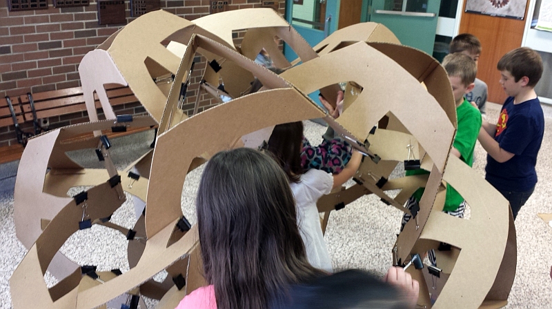
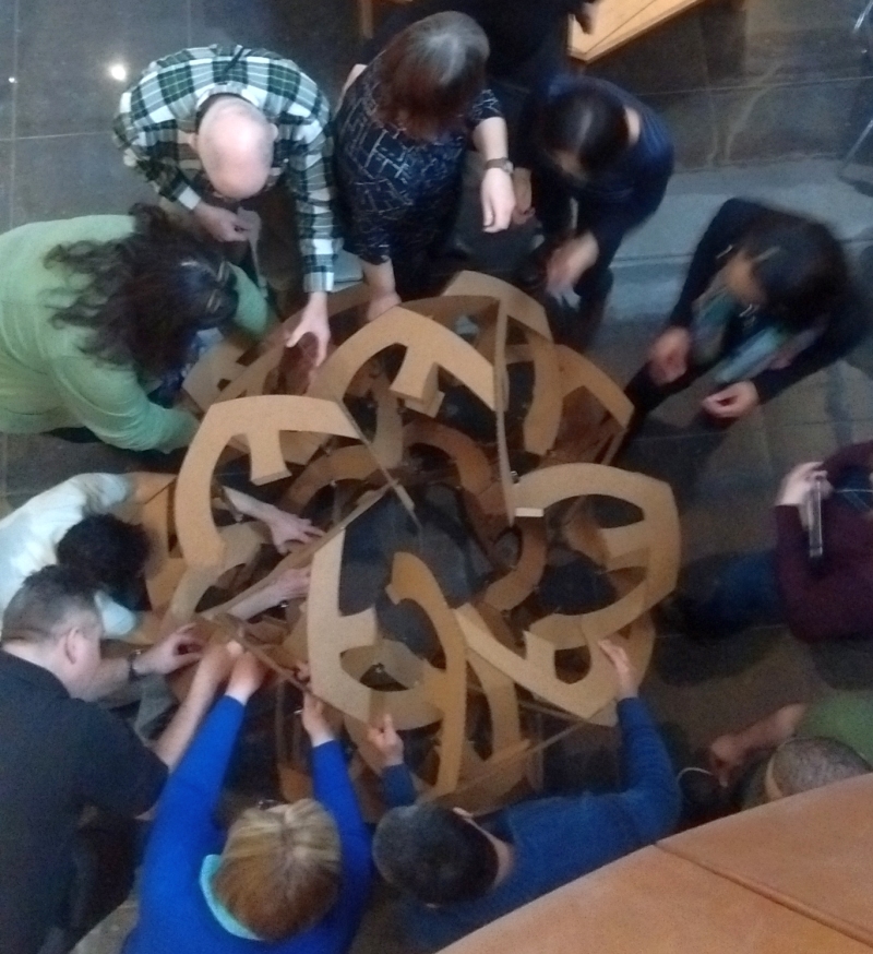
13. After everything is clamped together and checked for correctness, students can remove clamps one at a time, brush glue on the flap, and replace the clamps. It is easiest to work in pairs: one person handles a glue palette and glue brush while their partner manipulates the clamps and flaps.  If using black binder clamps, one handle of the clamp can be folded flat as a mark that the corner has been glued.  Students can work from all sides at once, looking at the clamp handles to locate any unmarked corners that need glue.  If using clothes pins, improvise some way to distinguish which flaps have been glued.  It works well to first do just the top half, then turn it over to do the other half. 


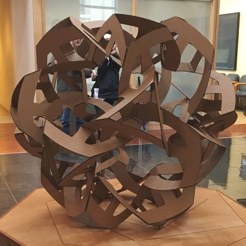
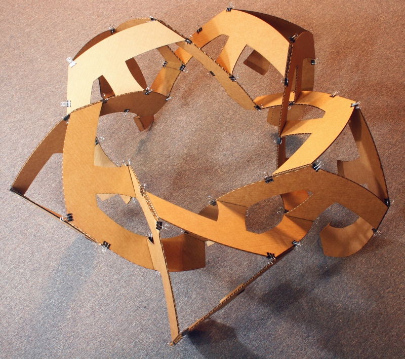
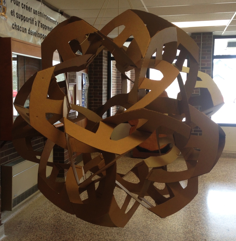
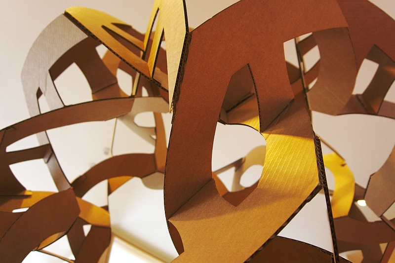
14. After the glue dries (typically 15 minutes) the clamps can be removed.  Hang the completed construction on display.


Part C. Conclusion

1. Students should be able to see how the design relates to an icosahedron with twenty triangular units, but it also has an inner layer of 3-fold vertices---one inside each triangle.  They may also notice how the parts are co-planar in sets of three.  For each part there are two others in its same plane.  So the sixty parts lie in just twenty planes.  They may hypothesize (correctly) that these are the planes of an (imagined) icosahedron.  For each plane of three parts, there is also a parallel plane of three parts, corresponding to the opposite face of the icosahedron.

2. Students should see that the design is chiral.  By looking at it in a mirror or simply imagining how its mirror-reflection would look, students should discover that its mirror-image version could be made from the same part template, but folding the flaps in the other direction.  If you have lots of energy, you can make a second one in the opposite handedness and display the matched enantiomorphic pair.
 
Possible Extensions

1. The design can be understood as deriving from the compound of five tetrahedra with the vertices of the tetrahedra being truncated and slightly rounded.  Three co-planar parts together outline one triangle from one regular tetrahedron.  So you can make a five-colored version in which each of the five tetrahedra is one color.  Paint the sixty parts in five colors: twelve parts in each color.  Assemble them into modules so each module is a single color.  When making the initial cycle of five modules, use one of each of the five colors.  After that, when adding the remaining fifteen modules, just be sure parallel faces are the same color.


Note: This design is the foundation for a large wood sculpture which starts from this spherical form and compresses it along one axis, transforming it into an oblate spheroid.